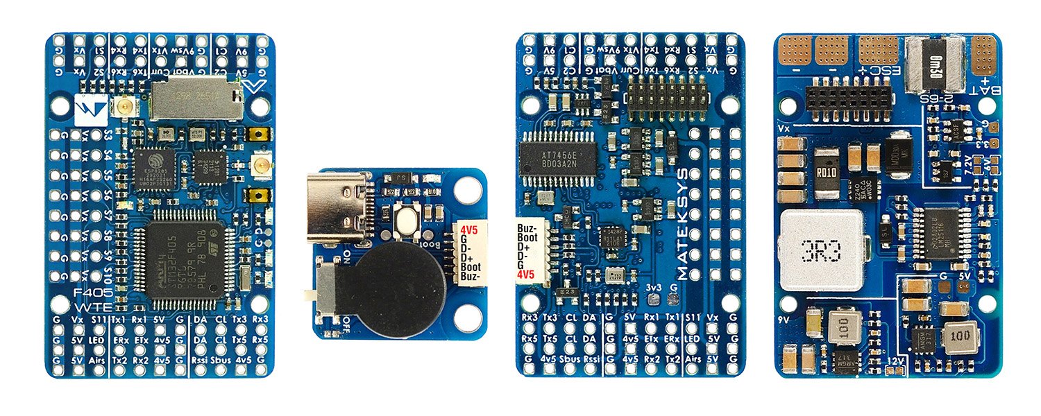
FC Specifications
- MCU: STM32F405RGT6, 168MHz , 1MB Flash
- IMU: ICM42688-P
- Baro: SPL06-001
- OSD: AT7456E
- Blackbox: MicroSD card slot
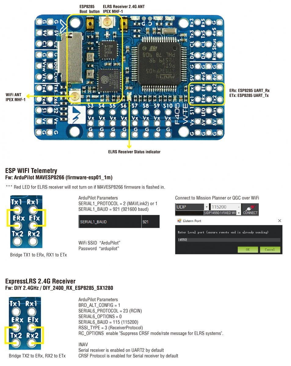
- ESP WiFi Telemetry(MAVLink, 14dBm)
- ExpressLRS 2.4G receiver(CRSF protocol, Telemetry 12dBm)
- 6x UARTs, 1x Softserial_Tx option(INAV)
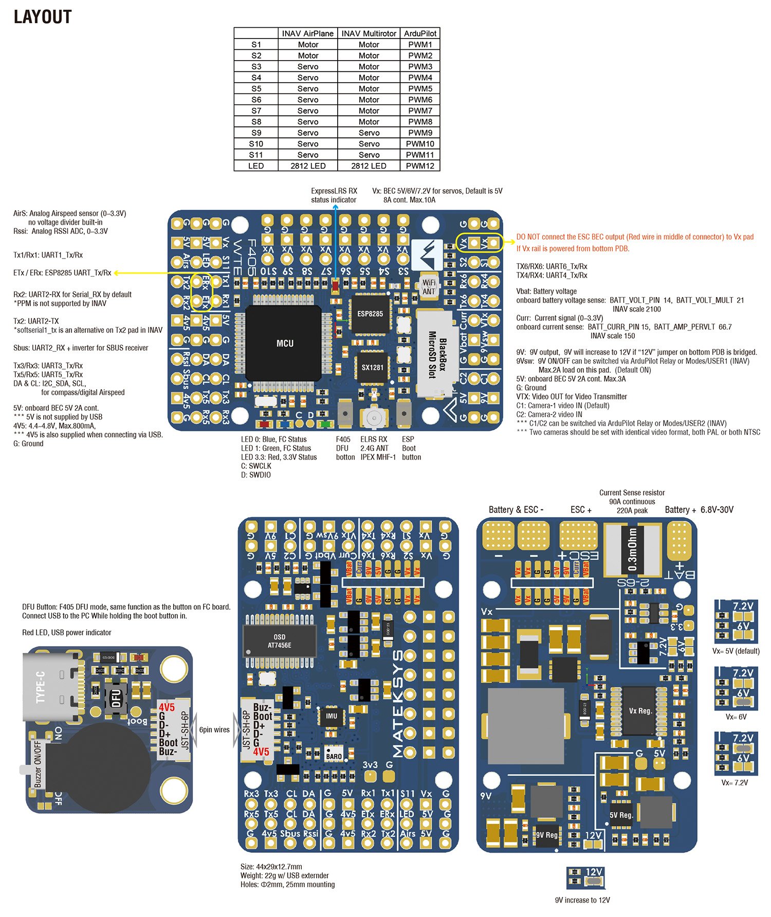
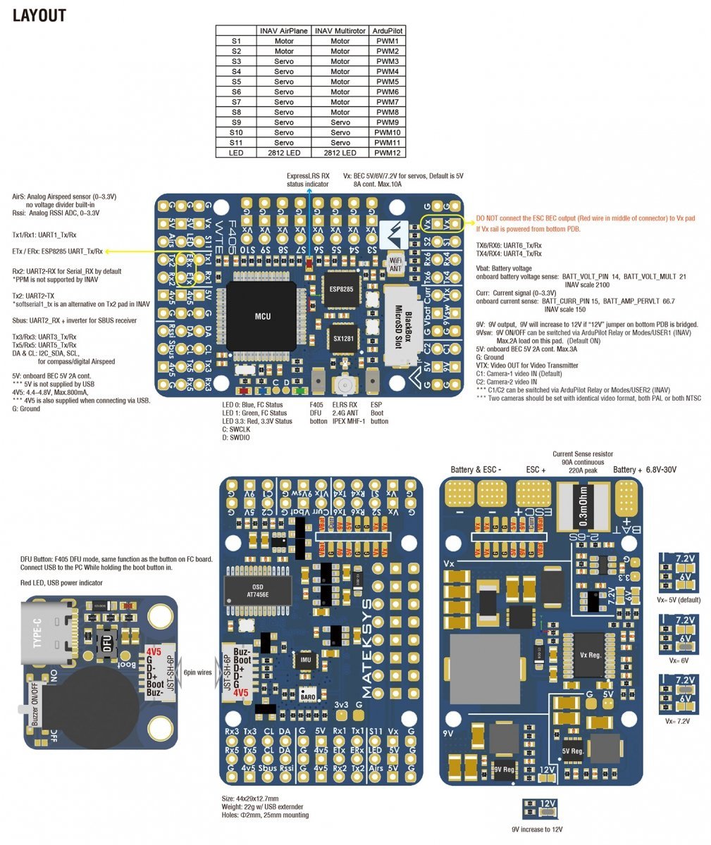
- 12x PWM outputs
- 1x I2C
- 4x ADC (VBAT, Current, RSSI, Airspeed)
- USB/Beep Extender with Type-C(USB2.0)
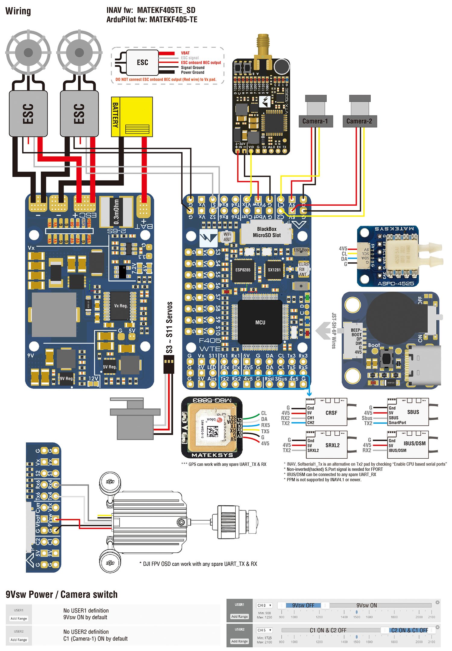
- Dual Camera Inputs switch
- 9V(12V) for VTX power switch
FC Firmware
- ArduPilot: MatekF405-TE
- INAV: MATEKF405TE_SD (not available in INAV configurator 4.x)
PDB
- Input voltage range: 6.8~30V (2~6S LiPo)
- 1x ESC power pads
- Battery Voltage divider 1K:20K (Scale 2100 in INAV, BATT_VOLT_MULT 21.0 in ArduPilot)
- Current Senor: 220A, 3.3V ADC (Scale 150 in INAV, 66.7 A/V in ArduPilot)
- Sense resistor: 90A continuous, 220A peak
BEC 5V output
- Designed for Flight controller, Receiver, OSD, Camera, Buzzer, 2812 LED_Strip, Buzzer, GPS module, AirSpeed
- Continuous current: 2 Amps, Max.3A
BEC 9V /12V output
- Designed for Video Transmitter, Camera, Gimbal ect.
- Continuous current: 2 Amps, Max.3A
- 12V option with Jumper pad
- for stable 9V/12V output, input voltage should > output voltage +1V
BEC Vx output
- Designed for Servos
- Voltage adjustable, 5V Default, 6V or 7.2V via jumper
- Continuous current: 8 Amps, Max.10A
- for stable Vx output, input voltage should > Vx voltage +1V
BEC 3.3V output
- Designed for Baro / Compass module and external 3.3V peripherals
- Linear Regulator
- Continuous current: 200mA
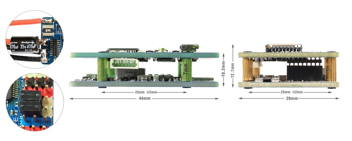
Physical
- Mounting: 25 x 25mm, Φ2mm
- Dimensions: 44 x 29 x 12.7mm
- Weight: 22g w/ USB/buzzer adapter
Including
- 1x F405-WTE
- 1x USB(Type-C)/Beep (Passive buzzer) Extender + 20cm JST-SH-6P to JST-SH-6P cable for USB extender.
- 2x IPEX-MHF1 2.4G Antennas
- 1x Rubycon ZLH 35V 470uF capacitor
- Dupont 2.54 pins (Board is shipped unsoldered)
ArduPilot ESP8266 wifi telemetry
- https://ardupilot.org/copter/docs/common-esp8266-telemetry.html
- Tool: ESP_NodeMCU-PyFlasher.exe
- Firmware: firmware-esp01_1m.bin
- Flashing with ESP_NodeMCU-PyFlasher
- Wire the ESP8285(ETx, ERx) into the USB-TTL adapter, with ETx on F405-WTE connected to the Rx on the USB-TTL, and ERx connected to the Tx of the USB-TTL. Wire 4v5 and GND of F405-WTE to 5V and GND of the USB-TTL
- Connect USB-TTL Adapter to PC while pressing and holding the ESP8285 boot button in.
- open ESP_NodeMCU-PyFlasher
- select Serial port of USB-TTL module, load firmware, select “Dual Output(DOUT)” and “Yes.wipes all data“
- click “Flash NodeMCU“
- after flashing, Power off , then power on F405-WTE by USB or Battery.
- Wait a few seconds, search WiFi SSID “ArduPilot”, and password is “ardupilot”
- Tips: Red LED for ELRS receiver will not turn on if MAVESP8266 firmware is flashed in.
ExpressLRS 2.4G Receiver
- https://www.expresslrs.org/2.0/quick-start/getting-started/
- ExpressLRS AUX1-AUX8 are not full resolution CH. https://www.expresslrs.org/2.0/software/switch-config/
- Flashing via WiFi
- Power on F405-WTE by USB, Receiver’s LED(Red) will blink slow at first, and after 30s, it should blink fast indicating it’s on WiFi Hotspot Mode.
- More detailed steps, pls refer this page.
- Target: DIY 2.4GHz / DIY_2400_RX_ESP8285_SX1280
- Flashing via UART
- Wire the ESP8285(ETx, ERx) into the USB-TTL adapter, with ETx on F405-WTE connected to the Rx on the USB-TTL, and ERx connected to the Tx of the USB-TTL. Wire 4v5 and GND of F405-WTE to 5V and GND of the USB-TTL.
- Connect USB-TTL Adapter to PC while pressing and holding the ESP8285 boot button in.
- Select the target DIY 2.4GHz / DIY_2400_RX_ESP8285_SX1280 and “UART” for Flashing Method, set your bind phrase and Firmware Options and once done, click on Build and Flash.
| INAV Mapping |
INAV MultiRotor |
INAV Plane |
| PWM |
S1 |
5 V tolerant I/O |
TIM8_CH4 |
Motor |
Motor |
| S2 |
5 V tolerant I/O |
TIM8_CH3 |
Motor |
Motor |
| S3 |
5 V tolerant I/O |
TIM1_CH3N |
Motor |
Servo |
| S4 |
5 V tolerant I/O |
TIM1_CH1 |
Motor |
Servo |
| S5 |
5 V tolerant I/O |
TIM2_CH4 |
Motor |
Servo |
| S6 |
5 V tolerant I/O |
TIM2_CH3 |
Motor |
Servo |
| S7 |
5 V tolerant I/O |
TIM2_CH2 |
Motor |
Servo |
| S8 |
5 V tolerant I/O |
TIM2_CH1 |
Motor |
Servo |
| S9 |
5 V tolerant I/O |
TIM12_CH1 |
Servo |
Servo |
| S10 |
5 V tolerant I/O |
TIM13_CH1 |
Servo |
Servo |
| S11 |
5 V tolerant I/O |
TIM4_CH1 |
Servo |
Servo |
| LED |
5 V tolerant I/O |
TIM3_CH4 |
2812LED |
2812LED |
| |
| ADC |
Vbat Pad |
1K:20K divider builtin
0~30V |
Vbat ADC
ADC_CHANNEL_1 |
INAV voltage scale 2100 |
| Curr pad |
0~3.3V |
Current ADC
ADC_CHANNEL_2 |
scale 150 |
| RSSI Pad |
0~3.3V |
RSSI ADC
ADC_CHANNEL_3 |
Analog RSSI |
| AirS Pad |
no divider builtin
0~3.3V |
AirS ADC
ADC_CHANNEL_4 |
Analog Airspeed |
| |
| I2C |
I2C1 |
5V tolerant I/O |
Compass |
QMC5883 / HMC5883 /MAG3110 / LIS3MDL |
| OLED |
0.96″ |
| onboard Barometer |
SPL06-001 |
| Digital Airspeed sensor |
MS4525 |
| Temperature sensor |
|
| |
UART
5V tolerant I/O |
USB |
|
USB |
|
| TX1 RX1 |
5V tolerant I/O |
UART1 |
USER |
| TX3 RX3 |
UART3 |
USER |
| TX4 RX4 |
UART4 |
USER |
| TX5 RX5 |
UART5 |
USER |
| TX6 RX6 |
UART6 |
USER |
TX2 RX2
SBUS |
5V tolerant I/O |
UART2 |
RC input/Receiver |
| Sbus pad |
for SBUS receiver, Sbus pad = RX2+inverter |
| RX2 pad |
IBUS/DSM/PPM |
| TX2 & RX2 |
CRSF |
| TX2 pad |
SmartPort Telemetry |
enable Softserial_Tx1 |
| TX2 pad |
FPORT, uninverted S.Port/F.Port signal (hacked) |
| TX2 pad |
SRXL2 |
| ArduPilot mapping |
PWM
5V tolerant I/O |
S1 |
PWM1 GPIO50 |
TIM8_CH4 |
DMA/DShot |
Group1 |
| S2 |
PWM2 GPIO51 |
TIM8_CH3 |
DMA/DShot |
| S3 |
PWM3 GPIO52 |
TIM1_CH3N |
DMA/DShot |
Group2 |
| S4 |
PWM4 GPIO53 |
TIM1_CH1 |
DMA/DShot |
| S5 |
PWM5 GPIO54 |
TIM2_CH4 |
DMA/DShot |
Gourp3 |
| S6 |
PWM6 GPIO55 |
TIM2_CH3 |
DMA/DShot |
| S7 |
PWM7 GPIO56 |
TIM2_CH2 |
DMA/DShot |
| S8 |
PWM8 GPIO57 |
TIM2_CH1 |
DMA/DShot |
| S9 |
PWM9 GPIO58 |
TIM12_CH1 |
NO DMA |
Gourp4 |
| S10 |
PWM10 GPIO59 |
TIM13_CH1 |
NO DMA |
Gourp5 |
| S11 |
PWM11 GPIO60 |
TIM4_CH1 |
NO DMA |
Gourp6 |
| LED pad |
PWM12 GPIO61 |
TIM3_CH4 |
DMA/DShot |
Gourp7 |
| SERVO12_FUNCTION 120, NTF_LED_TYPES neopixel |
Mixing Dshot and normal PWM operation for outputs is restricted into groups, ie. enabling Dshot for an output in a group requires that ALL outputs in that group be configured and used as Dshot, rather than PWM outputs.
If servo and motor are mixed in same group, make sure this group run lowest PWM frequency according to the servo specification. ie. Servo supports Max. 50Hz, ESC must run at 50Hz in this group. |
| |
| ADC |
Vbat Pad |
1K:20K divider builtin
0~30V |
Vbat ADC
onboard battery voltage
|
BATT_VOLT_PIN
BATT_VOLT_MULT |
14
21.0 |
| Curr pad |
0~3.3V |
current sensor ADC
onboard current sense
|
BATT_CURR_PIN
BATT_AMP_PERVLT |
15
66.7 |
| RSSI Pad |
0~3.3V |
RSSI ADC
Analog RSSI |
RSSI_ANA_PIN
RSSI_TYPE |
8
2 |
| AirS Pad |
no divider builtin
0~3.3V |
AirS ADC
Analog Airspeed |
ARSPD_PIN
ARSPD_TYPE |
10
2 |
| |
| I2C |
I2C1 |
5V tolerant I/O |
Compass |
COMPASS_AUTODEC |
1 |
| onboard Baro SPL06-001 |
Address |
0x76 |
Digital Airspeed I2C
MS4525
DLVR-L10D |
ARSPD_BUS
ARSPD_TYPE
ARSPD_TYPE |
1
1
9 |
| |
UART
5V tolerant I/O |
USB |
USB |
|
console |
SERIAL0 |
| TX1 RX1 |
USART1 |
with DMA |
telem1 |
SERIAL1 |
| TX3 RX3 |
USART3 |
NO DMA |
telem2 |
SERIAL2 |
| TX5 RX5 |
UART5 |
NO DMA |
GPS1 |
SERIAL3 |
| TX4 RX4 |
UART4 |
NO DMA |
DJI OSD |
SERIAL4 |
| TX6 RX6 |
USART6 |
TX6 with DMA |
USER |
SERIAL5 |
TX2 RX2
SBUS |
USART2 |
with DMA |
RC input/Receiver |
SERIAL6 |
| RX2 |
IBUS/DSM/PPM |
BRD_ALT_CONFIG 0
Default |
| Sbs pad |
SBUS |
| TX2 & RX2 |
CRSF |
BRD_ALT_CONFIG 1
SERIAL6_PROTOCOL 23 |
SERIAL6_OPTIONS 0 |
| TX2 |
uninverted FPort (hacked) |
SERIAL6_OPTIONS 4 |
| TX2 |
SRXL2 |
SERIAL6_OPTIONS 4 |
- set LOG_BACKEND_TYPE = 1 (File) for SD card logging
- If sending highspeed serial data (eg. 921600 baud) to the board, use USART1(Serial1) or USART2(Serial6).
Frsky Smartport Telemetry
- non-inverted (hacked) S.Port signal
- any spare Uart_TX
- SERIALx_BAUD 57
- SERIALx_OPTIONS 7
- SERIALx_PROTOCOL 4 or 10(for yaapu)
DJI FPV OSD (ArduPilot 4.1)
https://ardupilot.org/plane/docs/common-msp-osd-overview.html
- OSD_TYPE = 3
- SERIALx_PROTOCOL = 33
- MSP_OPTIONS = 0 (polling mode)
Relay(PINIO)
- PINIO1, 9Vsw power switch, On by default
- PINIO2, Camera switch, C1 ON by default
# GPIOs
- PA4 PINIO1 OUTPUT GPIO(81) LOW //9Vsw pad power switch
- PB5 PINIO2 OUTPUT GPIO(82) LOW //camera switch
# RCx_OPTION: RC input option
- 28 Relay On/Off
- 34 Relay2 On/Off
- 35 Relay3 On/Off
- 36 Relay4 On/Off
e.g.
- RELAY_PIN 81 //9Vsw GPIO
- RC7_OPTION 28 //Relay On/Off, Use CH7 of Transmitter to control 10V ON/OFF
- RELAY_PIN2 82 //Camera switch GPIO
- RC8_OPTION 34 //Relay2 On/Off, Use CH8 of Transmitter to control high/low level on PB5 pad
The configured feature will be triggered when the auxiliary switch’s pwm value becomes higher than 1800. It will be deactivated when the value falls below 1200.
Check the pwm value sent from the transmitter when the switch is high and low using the Mission Planner’s Initial Setup >> Mandatory Hardware >> Radio Calibration screen. If it does not climb higher than 1800 or lower than 1200, it is best to adjust the servo end points in the transmitter.
Tips
- F405-WTE has INAV fw 4.1.0 preloaded for QC
- Download INAV firmware 4.1.x from our website. Target MATEKF405TE_SD is not listed in INAV configurator 4.x.x, It will be supported by INAV5.0.
- ESP8285 has ExpressLRS fw 2.x preloaded with binding phrase “123456”, the Receiver will never enter binding mode if using the traditional binding procedure. It must be flashed without a binding phrase to do traditional binding OR flashed with your binding phrase.
- ArduPilot fw, set LOG_BACKEND_TYPE = 1 (File) for SD card logging
| |
F405-WTE |
F405-WSE |
| IMU |
ICM42688-P |
MPU6000 |
| Barometer |
SPL06-001 |
DPS310 |
| UARTs |
6 |
6 |
| I2C |
1 |
2 |
| PWM |
11+1 |
9+1 |
| ADC |
4 |
3 |
| Current sensor |
220A/90A |
132A/60A |
| Regulators |
5V, 2A
9V/12V, 2A
Vx, 8A |
5V, 2A
8V, 1.5A
Vx, 5A |
| ESP TLM / ELRS RX |
built-in |
/ |
| PINIO |
2 (Camera, 9Vsw) |
/ |
| INAV |
MatekF405TE_SD |
MatekF405SE |
| ArduPilot |
MatekF405-TE |
MatekF405-WING
|


![Super Silicone Wire 12AWG [3,0mm²] 1mb Czarny](https://static3.redcart.pl/templates/images/thumb/23617/150/150/pl/0/templates/images/products/23617/0ca2ecc2b64c8da127ac0ef5b30a5640.jpg "Super Silicone Wire 12AWG [3,0mm²] 1mb Czarny")
![Super Silicone Wire 12AWG [3,0mm²] 1mb Czerwony](https://static4.redcart.pl/templates/images/thumb/23617/150/150/pl/0/templates/images/products/23617/67ae93e92f6050ace57c498b3be73ecc.jpg "Super Silicone Wire 12AWG [3,0mm²] 1mb Czerwony")
